- Joined
- Jan 25, 2024
- Messages
- 12,301
- Points
- 38
- Age
- 39
- Location
- USA
- Website
- gameparadise.org
- Credits
- 206,669
This is the R&D thread. This is for people who want to know the nitty gritty of making their own dongle from sources, and has my thoughts through each stage of my process.
The user-friendly "Do this, this, this and this" tutorial will come after.
Disclaimer out of the way-- Here we go.
_________GREAT BIG EDIT____________
Ok. First up, the zsun is a "much soldering required" solution. My garbage hands are too shaky to even try this again. However, it will require an external power supply of some kind as the NX does not supply voltage on the USB voltage rail when in RCM mode. This means that in addition to the soldering hack to disable the card-reader and pass the port directly to the SOC, you will need some kind of battery. The contact points are tiny. VERY tiny. A small fraction of a millimeter tiny.
For these reasons, I recommend going with a platform that is much easier to work with. Currently, there are 2 major choices:
1) Fusee-lede based injectors
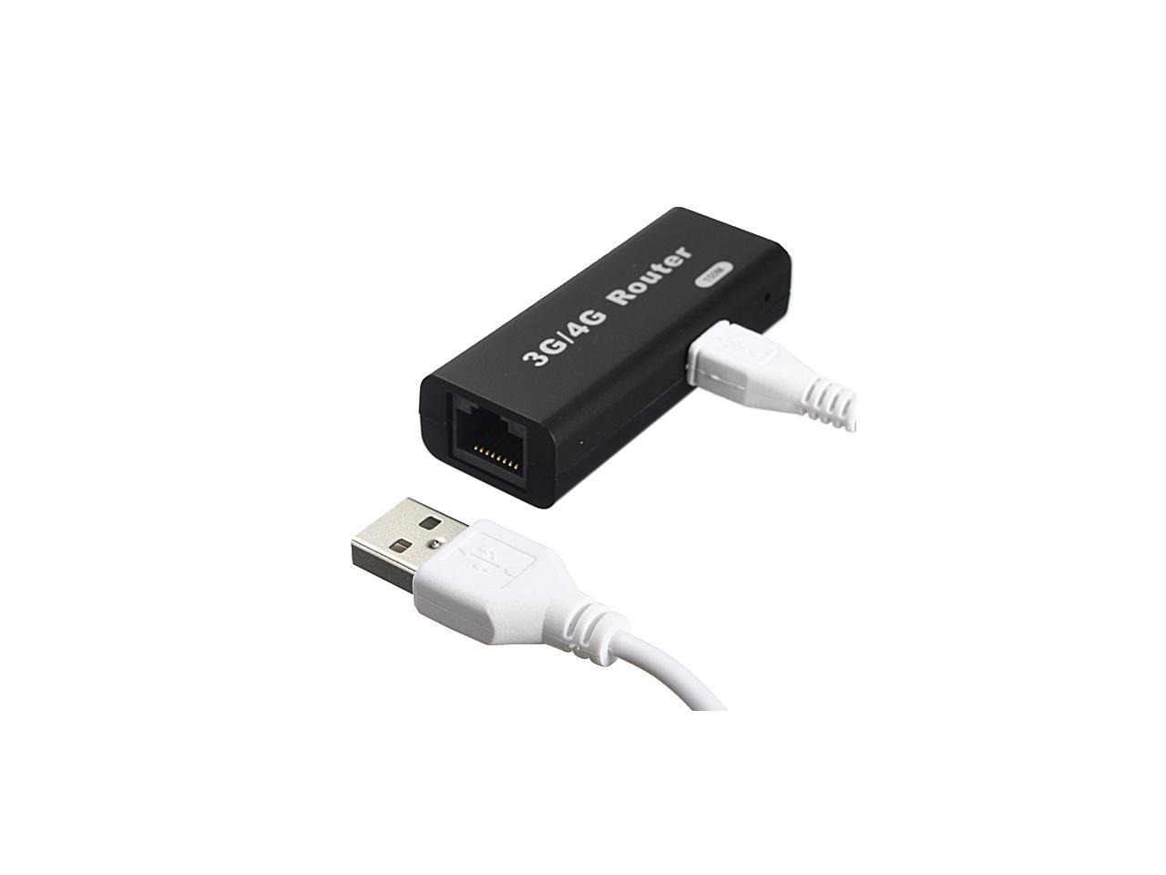
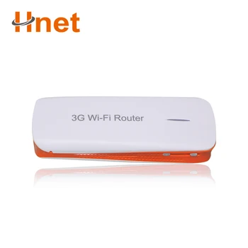
This is a flashable image for the "unbranded" A5-V11 hardware platform. This hardware is mostly known as something along the lines of "3G router 150m" and the like.. It comes in multiple hardware revisions, and two major form factors. One of the form factors is "without battery", while the other contains a useful battery and a power switch.
They look like this, respectively:
WITHOUT BATTERY

WITH BATTERY

There are now at least 5 builds of flashable images for this hardware that verious people have built. All are based on the initial modified lede instructions and injector code supplied by Retr0id. (read further into the thread, or search for 'fusee-lede')
***CAUTION***
This hardware has many many many internal hardware variations! While this is in theory a "cheap, solderless, and mostly painless" off-the-shelf solution, the factory of origin is still unknown, there is no known means to identify which internal hardware variant you are getting when you buy one, and there are several reports of bricked devices which likely stem from this hardware non-uniformity.
This same code-base is meant for just about any router or device that openWRT or LEDE supports, so it can be built for more devices than can be counted. The targeted platform for the project was the cheap chinese "3g router" specified however. It can be built for a very wide assortment of devices that support openwrt/lede, as long as the device has a USB2 port that can do host-mode.
PROS:
--SOLDERLESS
--INEXPENSIVE
--COMES WITH NICE INJECTION MOLDED HOUSING
--CAN PERFORM ANCILLARY FUNCTIONS (local file server, DNS host, Wifi bridge, etc.)
CONS:
--HARDWARE ROULETTE
--SLOW (Device takes ~30 seconds to boot itself before it can perform injections)
2)
Trinket M0 based injector(s)
These are devices based around the Adafruit Trinket M0, and Feather M0. The hardware is very uniform, as Adafruit does not screw around. This requires soldering, but the work of building the binary image for these microcontrollers has already been completed. The solder points are nice through-holes (aside from the USB port, but you can use solderless solutions on those.) and the skill needed to perform the work is significantly reduced from that needed for the zsun. The feather M0 has built-in battery charge logic, and a convenient JST battery connector. Ninoh_fox gets the credits for building the first functioning unit. Several variations of this offering have appeared in various youtube videos of internalized modchips for the NX console, as the trinket M0 is already very small, and is very fast.
PROS:
--RELIABLE, CONSISTENT HARDWARE SOURCE
--FAST (Ready to inject in just a few milliseconds.)
--CAN BE INTERNALIZED
--NICE THROUGH-HOLE SOLDER POINTS
--VERY SMALL
CONS:
--REQUIRES SOLDERING
--MORE EXPENSIVE (in total) THAN FUSEE-LEDE
--LACKS SHELL
--LACKS BATTERY
-----------------
For posterity, here is the remainder of the original post.
First an old post from another discussion topic so it does not get lost--
I was really hoping to not have to do surgery on the dongle, but looking closely at the pictures of the PCB from the hacking documents/research, I am going to have to.
There will need to be some slight soldering modifications to the device so that host mode data pins are exposed through the port. This sadly means sacrificing either the ability for the device to read the sdcard slot, or for the device to function as an sdcard reader for the host. I am going to elect sacrificing the ability for the device to read the sdcard slot. (Picking option 1 below.)
The reasoning is simple:
The designers included a 2 output select highspeed switch
EditSign
(that is fully bidirectional), that (as currently wired), switches the SDCard reader's data pins between either the SoC's USB root hub, or the USB-A connector. (this means that as wired, the USB-A plug cannot talk to the host's root hub.)
We have two options:
1) (Make the USB-A interface become the item that gets switched)
De-solder the contact going into the highspeed switch where the SDCard interface board talks, and remove the 2 pin header from the daughter board
Solder 2 patch wires into the header holes on the daughter board
Solder 2 patch wires onto the USB-A connector's D+ and D- contact pads
VERY CAREFULLY cut the traces on the motherboard that connect the SW1 D+ and D- pads of the highspeed switch to the USB-A interface
Run the USB-A patch wires into the switch's input header holes
Run the SDCard reader's patch wires into the teeeeeny tiny contact points of the surface mount switch's SW1 points. (Or look for testpoints on the PCB, and connect there.)
2) (Make the SoC host interface become the item that gets switched)
Hunt down contact points for the SoC's D+ and D- lines, and attach jumper wires
VERY CAREFULLY cut the traces after the SoC contact points we are using that lead to the switch
Desolder and remove the 2 pin header from the SDCard daughter board
Solder jumper wires to the header pin holes on the daughter board
Solder the SoC jumper wires to the switch input header pin holes
Solder the CardReader jumper wires to SW2 data pins (look for testpoints)
I think option 1 is less likely to have issues. (I dont have to hunt for as many test pads, and it should be easier to cut the traces) It will also allow the console to read the SDCard slot after the appropriate GPIO is asserted. Access to the RCM mode console is enabled because the highspeed switch is bidirectional, when the GPIO is low. The downside is that the SoC cannot see or use the card reader.
Option 2 allows the SoC to see the card reader, but denies the console access to the slot. It is also harder to pull off I think.
Given the issues I have faced trying to get a suitable bare image for the zsun built (due to small SPI flash, only 16mb), I think "candidate 2" I linked previously is a no-go, (Only 4mb SPI flash) even though it would be solderless. (has fully exposed host interface) I will look into other options that could be done that are fully solderless, but they are more expensive, and I am not made of money. (For the cost of 2 hardware test articles, I could buy a switch game and have much more fun.)[/QUOTE]
Addendum:
There's also the "Super easy" choice where we sacrifice both, by unsoldering the two pins to the SDcard reader, jumpering straight to the data pins on the port, and hooking nothing else up. That would make the GPIO toggle basically be "Host connected to port." and "Nothing connected." (actually, port connected to itself, so nothing.)
For simplicity, I will take this last option until I more completely explore this device.
----
And now for the fun part.
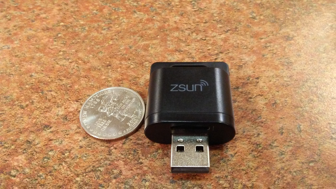
The dongle has arrived.
It's much smaller than I expected.

Initial research:
Device comes stock with an ancient linux kernel, and hyper-minimal embedded linux userspace. (2.6.31 !! BLECH!!)
Device's USB driver is NOT baked into the kernel; It is loaded as a module.
Device's root file system is writable!? (No, it's NOT tmpfs! It's totally jffs2!)
Device has root access via hidden telnet on port 11880. Username: root Password: zsun1188
This means the option to just recompile ehci-hcd.ko with FoF's patch, and sideload python (without flashing openwrt) is possible, but I wont be doing that. (Already built openwrt, which while an old version, is much newer than this kernel. 3.xxx kernel.)
I have already dumped the partitions and backed them up. Going to attempt firmware update. (If I fail, I will solder serial console header on, and recover)
Wish me luck.
The user-friendly "Do this, this, this and this" tutorial will come after.
Disclaimer out of the way-- Here we go.
_________GREAT BIG EDIT____________
Ok. First up, the zsun is a "much soldering required" solution. My garbage hands are too shaky to even try this again. However, it will require an external power supply of some kind as the NX does not supply voltage on the USB voltage rail when in RCM mode. This means that in addition to the soldering hack to disable the card-reader and pass the port directly to the SOC, you will need some kind of battery. The contact points are tiny. VERY tiny. A small fraction of a millimeter tiny.
For these reasons, I recommend going with a platform that is much easier to work with. Currently, there are 2 major choices:
1) Fusee-lede based injectors
This is a flashable image for the "unbranded" A5-V11 hardware platform. This hardware is mostly known as something along the lines of "3G router 150m" and the like.. It comes in multiple hardware revisions, and two major form factors. One of the form factors is "without battery", while the other contains a useful battery and a power switch.
They look like this, respectively:
WITHOUT BATTERY

WITH BATTERY

There are now at least 5 builds of flashable images for this hardware that verious people have built. All are based on the initial modified lede instructions and injector code supplied by Retr0id. (read further into the thread, or search for 'fusee-lede')
***CAUTION***
This hardware has many many many internal hardware variations! While this is in theory a "cheap, solderless, and mostly painless" off-the-shelf solution, the factory of origin is still unknown, there is no known means to identify which internal hardware variant you are getting when you buy one, and there are several reports of bricked devices which likely stem from this hardware non-uniformity.
This same code-base is meant for just about any router or device that openWRT or LEDE supports, so it can be built for more devices than can be counted. The targeted platform for the project was the cheap chinese "3g router" specified however. It can be built for a very wide assortment of devices that support openwrt/lede, as long as the device has a USB2 port that can do host-mode.
PROS:
--SOLDERLESS
--INEXPENSIVE
--COMES WITH NICE INJECTION MOLDED HOUSING
--CAN PERFORM ANCILLARY FUNCTIONS (local file server, DNS host, Wifi bridge, etc.)
CONS:
--HARDWARE ROULETTE
--SLOW (Device takes ~30 seconds to boot itself before it can perform injections)
2)
Trinket M0 based injector(s)
These are devices based around the Adafruit Trinket M0, and Feather M0. The hardware is very uniform, as Adafruit does not screw around. This requires soldering, but the work of building the binary image for these microcontrollers has already been completed. The solder points are nice through-holes (aside from the USB port, but you can use solderless solutions on those.) and the skill needed to perform the work is significantly reduced from that needed for the zsun. The feather M0 has built-in battery charge logic, and a convenient JST battery connector. Ninoh_fox gets the credits for building the first functioning unit. Several variations of this offering have appeared in various youtube videos of internalized modchips for the NX console, as the trinket M0 is already very small, and is very fast.
PROS:
--RELIABLE, CONSISTENT HARDWARE SOURCE
--FAST (Ready to inject in just a few milliseconds.)
--CAN BE INTERNALIZED
--NICE THROUGH-HOLE SOLDER POINTS
--VERY SMALL
CONS:
--REQUIRES SOLDERING
--MORE EXPENSIVE (in total) THAN FUSEE-LEDE
--LACKS SHELL
--LACKS BATTERY
-----------------
For posterity, here is the remainder of the original post.
First an old post from another discussion topic so it does not get lost--
I was really hoping to not have to do surgery on the dongle, but looking closely at the pictures of the PCB from the hacking documents/research, I am going to have to.
There will need to be some slight soldering modifications to the device so that host mode data pins are exposed through the port. This sadly means sacrificing either the ability for the device to read the sdcard slot, or for the device to function as an sdcard reader for the host. I am going to elect sacrificing the ability for the device to read the sdcard slot. (Picking option 1 below.)
The reasoning is simple:
The designers included a 2 output select highspeed switch
EditSign
(that is fully bidirectional), that (as currently wired), switches the SDCard reader's data pins between either the SoC's USB root hub, or the USB-A connector. (this means that as wired, the USB-A plug cannot talk to the host's root hub.)
We have two options:
1) (Make the USB-A interface become the item that gets switched)
De-solder the contact going into the highspeed switch where the SDCard interface board talks, and remove the 2 pin header from the daughter board
Solder 2 patch wires into the header holes on the daughter board
Solder 2 patch wires onto the USB-A connector's D+ and D- contact pads
VERY CAREFULLY cut the traces on the motherboard that connect the SW1 D+ and D- pads of the highspeed switch to the USB-A interface
Run the USB-A patch wires into the switch's input header holes
Run the SDCard reader's patch wires into the teeeeeny tiny contact points of the surface mount switch's SW1 points. (Or look for testpoints on the PCB, and connect there.)
2) (Make the SoC host interface become the item that gets switched)
Hunt down contact points for the SoC's D+ and D- lines, and attach jumper wires
VERY CAREFULLY cut the traces after the SoC contact points we are using that lead to the switch
Desolder and remove the 2 pin header from the SDCard daughter board
Solder jumper wires to the header pin holes on the daughter board
Solder the SoC jumper wires to the switch input header pin holes
Solder the CardReader jumper wires to SW2 data pins (look for testpoints)
I think option 1 is less likely to have issues. (I dont have to hunt for as many test pads, and it should be easier to cut the traces) It will also allow the console to read the SDCard slot after the appropriate GPIO is asserted. Access to the RCM mode console is enabled because the highspeed switch is bidirectional, when the GPIO is low. The downside is that the SoC cannot see or use the card reader.
Option 2 allows the SoC to see the card reader, but denies the console access to the slot. It is also harder to pull off I think.
Given the issues I have faced trying to get a suitable bare image for the zsun built (due to small SPI flash, only 16mb), I think "candidate 2" I linked previously is a no-go, (Only 4mb SPI flash) even though it would be solderless. (has fully exposed host interface) I will look into other options that could be done that are fully solderless, but they are more expensive, and I am not made of money. (For the cost of 2 hardware test articles, I could buy a switch game and have much more fun.)[/QUOTE]
Addendum:
There's also the "Super easy" choice where we sacrifice both, by unsoldering the two pins to the SDcard reader, jumpering straight to the data pins on the port, and hooking nothing else up. That would make the GPIO toggle basically be "Host connected to port." and "Nothing connected." (actually, port connected to itself, so nothing.)
For simplicity, I will take this last option until I more completely explore this device.
----
And now for the fun part.
The dongle has arrived.
It's much smaller than I expected.

Initial research:
Device comes stock with an ancient linux kernel, and hyper-minimal embedded linux userspace. (2.6.31 !! BLECH!!)
Device's USB driver is NOT baked into the kernel; It is loaded as a module.
Device's root file system is writable!? (No, it's NOT tmpfs! It's totally jffs2!)
Device has root access via hidden telnet on port 11880. Username: root Password: zsun1188
This means the option to just recompile ehci-hcd.ko with FoF's patch, and sideload python (without flashing openwrt) is possible, but I wont be doing that. (Already built openwrt, which while an old version, is much newer than this kernel. 3.xxx kernel.)
I have already dumped the partitions and backed them up. Going to attempt firmware update. (If I fail, I will solder serial console header on, and recover)
Wish me luck.


